


Percutaneous catheter treatment for atrial fibrillation (AF) has seen an exponential uptake since the first cases were published exactly two decades ago.1 Evolving over different approaches and treatment strategies, current standard of care consists of pulmonary vein isolation (PVI) through radiofrequency (RF) or other energy sources. While this treatment has been shown to be superior to pharmacological treatment in the setting of paroxysmal AF, considerable variation in reported outcomes exists.2,3 Part of this variation is attributed to the aforementioned change in strategies over time – a clear evolution exists from electrophysiology (EP)-guided (and anatomically rather straightforward) approaches such as trigger elimination inside the pulmonary veins (PVs) to more empirical creation of circular lesions around the PVs.3 This latter approach eliminates challenges such as trigger identification and reduces safety concerns such as PV stenosis, but introduces new complexities that are mostly related to catheter positioning in the complex three-dimensional (3D) space of the left atrium (LA).
One of the peculiarities of catheter manipulation in the LA is the usefulness, or rather lack of usefulness, of basic two-dimensional (2D) fluoroscopy. Unlike conventional procedures (e.g. right atrial or ventricular manipulation), fluoroscopy landmarks for AF ablation are few and far between. On top of that, safe and successful PVI requires precise energy delivery at crucial complex 3D structures, such as the left superior PV left atrial appendage transition. In order to achieve this goal, several tools have been developed that either help the operator understand anatomy, facilitate 3D catheter navigation or decrease radiation exposure; and ideally combine several of these useful features.4–7
Rotational Angiography
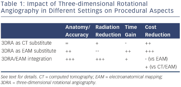
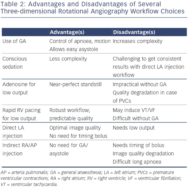
Three-dimensional rotational angiography (3DRA) is an innovative method that allows reconstruction of tomographic slices of a volume of interest in a manner similar to computed tomography (CT), using single-plane radiographic equipment.8,9 The reconstructed 3D models can be used instead of conventional CT or magnetic resonance imaging (MRI) to complement non-fluoroscopic navigation systems, or can be overlaid on 2D fluoroscopic images. In contrast to CT/MRI this technology allows near realtime 3D imaging that is acquired during an ongoing ablation procedure, thereby avoiding volume mismatch due to changes in volume status, rhythm or even table geometry (influencing chest geometry). Not only does 3DRA offer advantages in terms of accuracy over pre-procedural imaging, it also has important benefits from a logistics and cost-effectiveness perspective. Table 1 lists the impact of 3DRA in different clinical scenarios, explained below. Table 2 lists the impact of different workflow options for 3DRA.
Three-dimensional Rotational Angiography as Computed Tomography Substitute
At its core, 3DRA is a technology that produces CT-like tomography slices. These slices can be used to perform measurements or – more commonly for EP procedures – to make a 3D reconstruction of a structure of interest. Image integration is routinely performed for complex ablation procedures and has been shown to be useful in understanding potentially variant anatomy and enhancing procedural efficacy.4–6 Reconstructed 3DRA volumes correlate well with CT-derived volumes and can therefore be used as a substitute in this setting. Compared with CT, patient radiation exposure is reduced and can be brought to levels well below accepted values for interventional procedures.10 A workflow based on imaging in the EP lab allows logistic independence from other departments, making ‘on the spot’ decision trees possible. In addition, cost benefits are reasonable to expect as the incremental cost of performing a single 3DRA amounts to contrast agent and a pigtail catheter. Table 1 and 2 summarise the impact of using 3DRA in different scenarios.
Three-dimensional Rotational Angiography as Electroanatomical Mapping Substitute
Due to the aforementioned challenges in 3D navigation of the LA, electroanatomical mapping (EAM) has quickly evolved to become the de facto standard for guiding RF ablation.7 EAM allows an operator to reconstruct any geometry by navigating a catheter within the space of that geometry. The obvious drawback is that any geometry is ‘unknown’ at the beginning of the mapping phase – an operator needs to discover geometry in the course of the procedure. This means significant operator expertise is required and the potential for ‘missing’ certain parts of the anatomy is present – especially in cases of variant anatomy such as presence of a roof vein or other congenital anomalies. On top of that, some alternative approaches for PVI such as single-shot devices (balloon cryotherapy, multipolar RF) are not compatible with EAM systems. In these settings 3D LA visualisation is completely absent – positioning of these devices depends on assumptions of PV antrum shape for which purpose-built catheters are used, generally requiring 2D contrast injections to verify adequate placement.
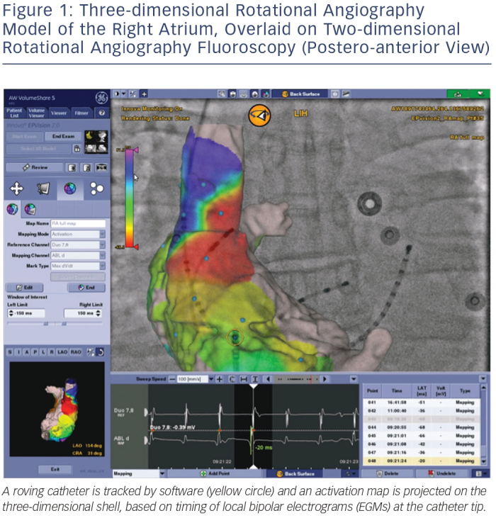
As an alternative to an EAM workflow or as a complement to a single-shot device workflow, 3DRA models can be overlaid on live fluoroscopy. As typically the same manufacturer provides the fluoroscopy equipment and the 3DRA segmentation workstation, these systems are linked and able to communicate with each other. This allows the fluoroscopy system to show an appropriately sized and rotated 3D model for any live 2D fluoroscopy angle an operator chooses. Modern systems allow tagging of points of interest (such as ablation sites for tracking), and most recent developments allow activation and substrate maps to be integrated in the 2D/3D model by linking an EP recording system to the setup (see Figure 1).
A purely 3DRA-based workflow has limitations compared with EAM, mainly due to the inherent 2D nature of the live fluoroscopy image and the physical constraints within which a fluoroscopy gantry needs to operate. Also, importantly, catheter visualisation is only possible using ongoing fluoroscopy exposure. However, from a cost perspective important gains are achievable because no high disposable cost is incurred – a 3DRA model as an EAM substitute may therefore make very good sense in well-selected clinical scenarios.
Three-dimensional Rotational Angiography and Electroanatomical Mapping Integration
Further integration of imaging modalities has led to the linking of existing fluoroscopy systems to EAM systems. This allows an EAM system to display 2D X-ray backgrounds corresponding to a particular orientation and fuse them with the 3D display. The intuitive application of such a feature is catheter positioning (e.g. coronary sinus placement) with minimal use of fluoroscopy. More importantly though, this integration means the fluoroscopy and EAM system now share a single coordinate system – any point in ‘true’ 3D space is defined precisely and identically in both systems. As a result of this, a linked fluoro-EAM system is able to display a 3DRA-derived volume in its correct position without having to collect even a single anatomy point from the catheter, eliminating any experience barrier and eliminating the potential for ‘missed’ regions of anatomy.
Combining the benefits of 3DRA (complete and detailed, CT-like anatomy) with the benefits of EAM (non-fluoroscopic catheter navigation) allows for a highly reproducible workflow for PVI that is potentially able to reduce procedural time (elimination of mapping time) and radiation exposure (near elimination of fluoroscopy for catheter manipulation) while maintaining a high standard of safety and efficacy (accurate 3D representation of the target structures of interest). The authors have developed such a workflow, which has been used in several hundred consecutive PVI procedures over the past 18 months.
Independent verification of the accuracy of the 3DRA/EAM integrated model, such as contact force sensing indicating contact at the visualised tissue wall, may allow an operator to develop enough confidence in the 3D model to use it exclusively – that is without requiring additional fluoroscopy once the 3DRA has been acquired. In such a workflow, given a high enough degree of spatial accuracy of the 3D map, fluoroscopy is only needed for initial setup, LA access and catheter placement. Routine exposure measurements in our lab using high sensitivity realtime digital dosimeters consistently confirm patient effective doses around 1 mSv (mainly from the 3DRA acquisition) and operator doses, measured outside the lead apron, around 1 μSv – well below daily natural background radiation and therefore in the range of completely insignificant exposure.
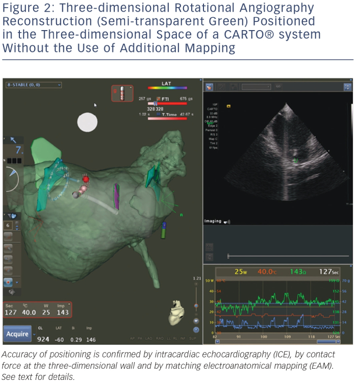
Figure 2 shows an example of such a resulting workflow, with EAM mapping and intracardiac echocardiography (ICE) mapping used for backup verification purposes. Of note are the 3DRA volume (semi-transparent green), the EAM volume (semi-transparent grey) and the ICE structures (solid green and purple, marking the left common ostium, the right inferior PV and the oesophagus). The 3DRA volume is positioned in the EAM system without any merging to the EAM shell – its position is determined by 3DRA/EAM integration. Contact is indicated by the EAM contact force measurement and confirmed on ICE. The EAM shell is significantly smaller than the 3DRA shell, in particular near the mitral valve where mapping is difficult and potentially dangerous (due to mapping catheter entrapment in the subvalvular apparatus). The ICE structures are accurate yet rudimentary due to incomplete visualisation from different angles. The 3DRA shell aligns exactly with the EAM ablation tags, which are generated automatically by the system based on contact and position stability – providing another independent verification of 3D model accuracy.
Alternative Realtime Imaging Modalities
Intracardiac Echocardiography
Currently, ICE is widely used as a realtime imaging modality in AF, in particular in the US – Medicare data suggests application in 67 % of PVI cases.11 The clear benefit of ICE over 3DRA is that it allows continuous realtime visualisation of geometry and catheter position without radiation exposure. Additional benefits may include transseptal puncture guidance, LA appendage thrombus assessment, monitoring for complications and visualisation of the oesophagus position. Transoesophageal echography can provide these additional benefits equally well but does not allow the first, clear benefit of realtime monitoring during ablation because of concerns regarding leaving a bulky echo probe in proximity to the LA posterior wall during RF application. However, a purely ICE-based workflow (without EAM integration) suffers from incomplete visualisation of anatomy and is again heavily dependent on operator skill and training. As a result, in most cases ICE is used in AF ablation cases for accessing the LA safely but discarded or only used as a complementary tool to EAM for the remainder of the procedure. Furthermore, disposable catheter costs are significant – resource allocation considerations in no-reuse environments have therefore led to much lower adoption rates outside the US.
Direct Visualisation
Laser balloon ablation is a recently described technique sharing features of single-shot approaches as well as point-by-point techniques.12 A unique feature of this approach is that the system contains an integrated endoscope allowing direct visualisation of the target structures for ablation. Although experience is limited, some centres have published long-term follow-up (four years) with encouraging results.13
Magnetic Resonance Imaging
MRI is already widely used in EP labs, mostly as a pre-procedural imaging technique offering either information about size/shape of cardiac chambers of interest or additional information such as identification of arrhythmia substrates (e.g. post-infarction scarring of the ventricle) to guide ablation. Furthermore, MRI has been shown to be very useful for lesion visualisation induced by RF with high spatial and temporal resolution, and for the identification of oedema (T2-weighted imaging) and necrosis using delayed enhancement (DE) imaging. MRI thus offers the potential benefit of delineating areas with permanent tissue damage, thereby guiding ablation and improving the procedural endpoints.14,15
For these reasons, realtime MRI (RTMRI) has been proposed as a new tool for guiding and monitoring EP procedures and ablations.16,17 While it is still in an early research phase, currently limited by extensive logistic and infrastructure requirements, technological advancements may well bring RTMRI into the clinical research setting in the near future, at which point additional benefits of MRI such as substrate visualisation may become significant.18
Conclusion
Technological advances have evolved the field of AF ablation – an anatomically challenging procedure is increasingly supported by advanced imaging solutions. These solutions are increasingly used synergistically by integrating different systems. Several established and novel approaches aim to provide an intuitive and maximally accurate representation of the LA and its specific anatomic regions in order to enhance procedural safety and efficacy during ablation. Of these, 3DRA is an imaging modality that is currently applicable in high-volume clinical settings, potentially as a stand-alone tool or integrated in 3D navigation systems – the latter allowing near-zero radiation workflows for PVI.